Hardware Repairs / 2020-12-27 20:27:17Most Amiga hardware has now more than 20 years... so, yes, it is getting wiser PS. Follow these tips at your own risks! I cannot (and won't) be responsible for any damage that you may cause!
Installing an ACA1230 or ACA1233The ACA1230 and ACA1233 are accelerators for the A1200 from Individual Computers. They are modern and clean-built accelerators, using surface mounted components. They are without mobile parts (no fans!) and therefore totally silent... They are also plug-and-play! The are actually very easy to install: just open up the trap door under the Amiga and gently slide them in, starting with the side with the "small connector" and twisting them straight to connect them tight. Then, close the trap, fire the Amiga, and enjoy!
Changing an Amiga 1200 PSU for a Modern, Standard ATX PSUThere are now lots of ATX PSU for sale for cheap in second-hand stores, which are in perfect conditions. They can be bought for less than $CA10 and used to effectively replace the old Amiga PSU with more power (watts) to support more extensions. There are a few steps to follow to use a ATX PSU:
Changing an Amiga 4000D PSU for a Modern, Standard ATX PSUI'm lucky to have a A4000 that works (still) very well, even its original PSU... but this PSU is 220V only and thus requires a heavy-duty, cumbersome, and ugly 110V-220V converter... Meanwhile, Meanwell produces sleak PSUs, perfect for an Amiga 4000. TUMO found the RPT-160B for me Using some spare 18 gauge wires, 8 molex female pins, heat-shrink tubing, and 18-poles screw terminals, a soldering iron, and some patience, I desoldered the wires going in and out of the old PSU and reconnected them to the new Meanwell and it works very well! On the original A4000D PSU, from the 6-pin, brown-redish, motherboard connector; the brown wire is the Power On Good signal:
In practice, this looks like:
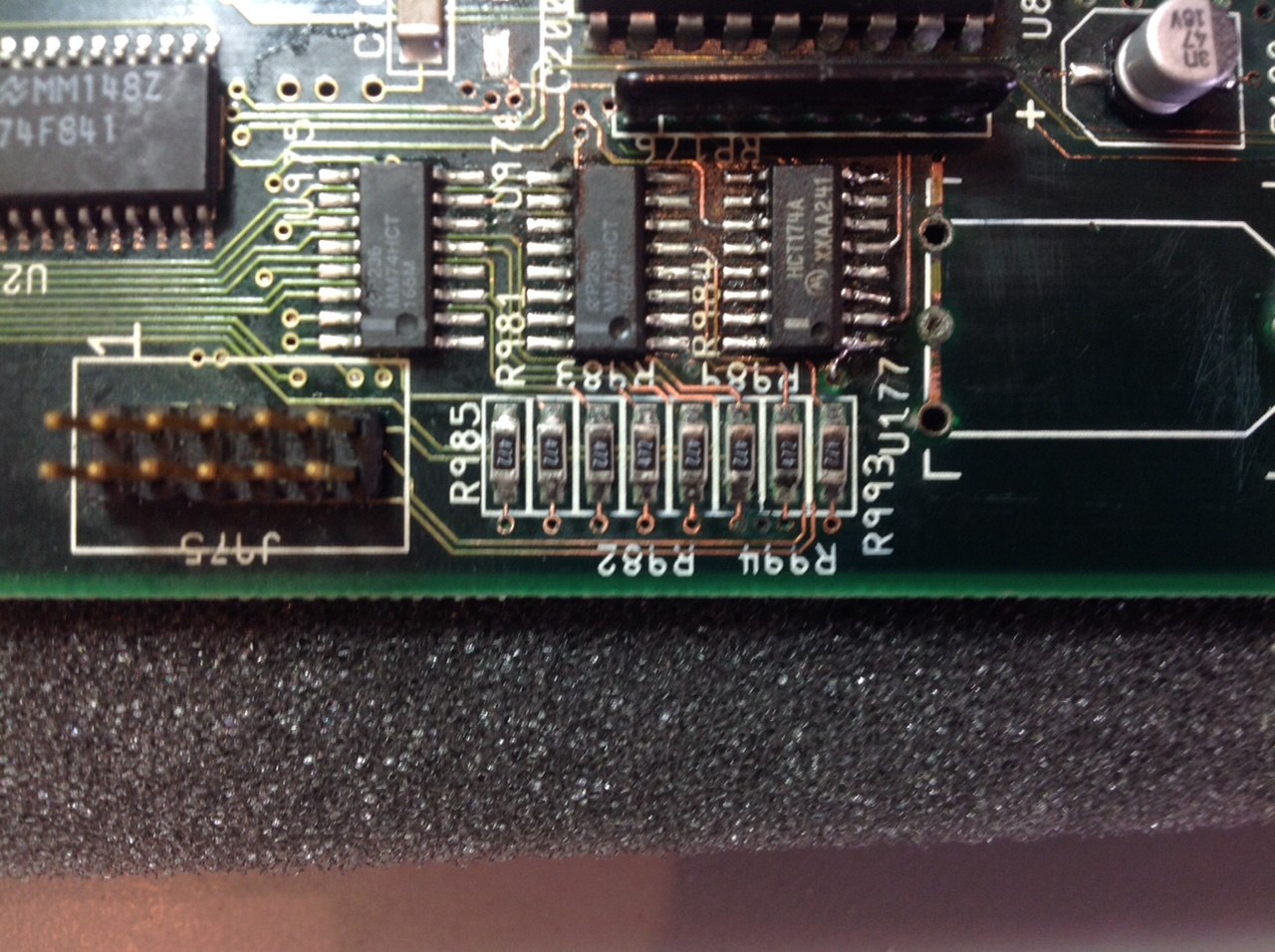
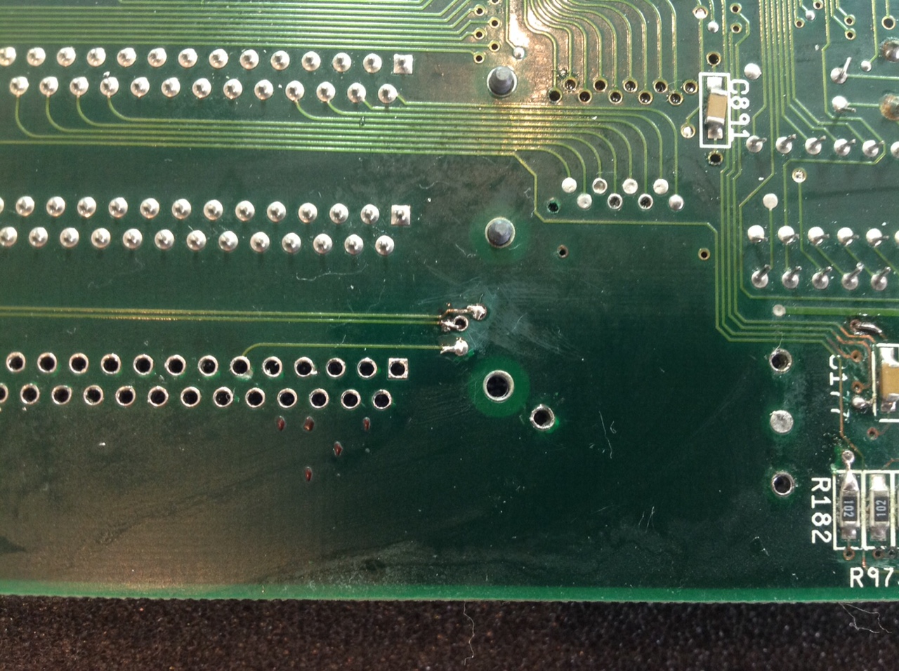
Fixing a A4000 Motherboard with Damage due to a Leaking BatteryI would not recommend trying to fix damage due to a leaking battery at home! Trust experts, like AmigaKit, even then find that difficult! In particular because the leak damaged "through holes" and connection under the memory sockets
Changing the Capacitors in the AmigsThe worst problem with Amigas, after a leaking battery, is malfunctioning capacitors... In old times, they used to use electrolytic capacitors, which are cheap(er) but have some limitations: they leak or they dry, at best loosing their properties, at worst damaging the motherboard. Fortunately, these capacitors can be replaced "easily" with modern, more expansive, but (very) long lasting cermaic capacitors. The differences between the too are too long to explain here and go waaay beyong my head anyways Here is a list of the capacitors per Amiga models/revision:
In Canada, these capacitors can be bought from DigiKey!
Connecting a Arananet and ENC28J60 moduleThe Vampire is an amazing card that really give a second life to the Amigas! It can be equipped with a combo Arananet + ENC28J60 module to provide an Ethernet port and access to the Internet using the SDNet driver Arananet PinsMy Arananet came with 12 pins and two soldered wires next to the 5V and GND pins. These two wires are not connected to the 5V and GND pins! I connected them to the 5V and GND pins (duh!) of my 12-pin ENC28J60 module. Now, there are two possible organisation of the pins. Trying one or the other should not damage anything. In my case, this organisation was correct:
5V   --   -- GND
     o1   2o INT
     o3   4o S0
SI   o5   6o SCK
CS   o7   8o
3.3V o9  10o GND
ENC28J60 Module PinsIn theory, the pins of a ENC28J60 module are: CLK o1 2o INT WOL o3 4o S0 SI o5 6o SCK CS o7 8o REST VCC o9 10o GND BUT, on my ENC28J60 module, the pins are as follows because there are two models of modules: with 10 or 12 pins! 5V o1 2o GND INT o3 4o CLK S0 o5 6o WOL SCK o7 8o SI RST o9 10o CS Q3 o11 12o GND So, at first, I also connected the 5V and GND pins from the Arananet to those of the ENC28J60 module. However, the Ethernet module was very unstable, often "powering off" and leading the driver to freeze or go into an infinite loop. I received help from people on the Apollo forum, in particular Henryk who gave me the solution: the Vampire and Arananet module provide +3.3V (actually, +2.8V according to my measures) instead of the expected +5V to the ConnectionsHere a table showing the correspondance (hence, the connections) between the two:
Note: GND 10o (even number) goes into GND 12o (also even number). The +5V must come from the floppy disk (brown wire) into the 5V (o1) pin of the ENC28J60 module. Thanks again XRay, guibrush, and Henryk!
| ||||||||||||||||||||||||||||||||||||||||||||||||||||||||||||||||||||||||||||||||||||||||||||||||||||||||||||||||||||||||||||||||||||||||||||||||||||||||||||||||||||||||||||||||||||||||||||||||||||||||||||||||||||||||||||||||||||||||||||||||||||||||||||||||||||||||||||||||||||||||||||||||||


 but also needs some repairs. Here are some repairs and tips.
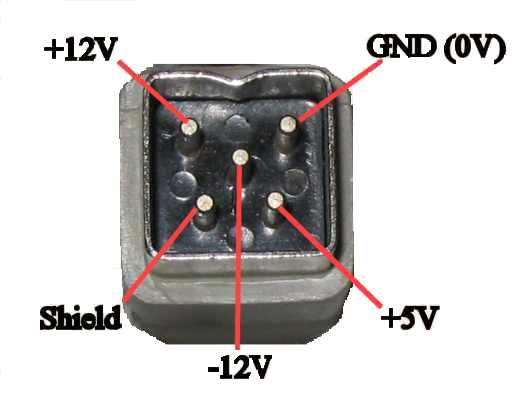

 . This PSU takes anything between 90V to 240V and
  .
._small.jpg)
_small.jpg)
_small.jpg)
_small.jpg)
_small.jpg)
_small.jpg)
_small.jpg)
_small.jpg)
 . Here are some pictures of the step to fix the damage, courtesy of AmigaKit:


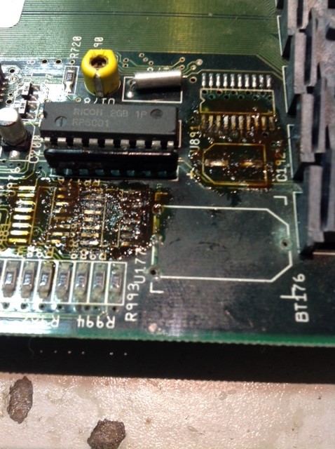


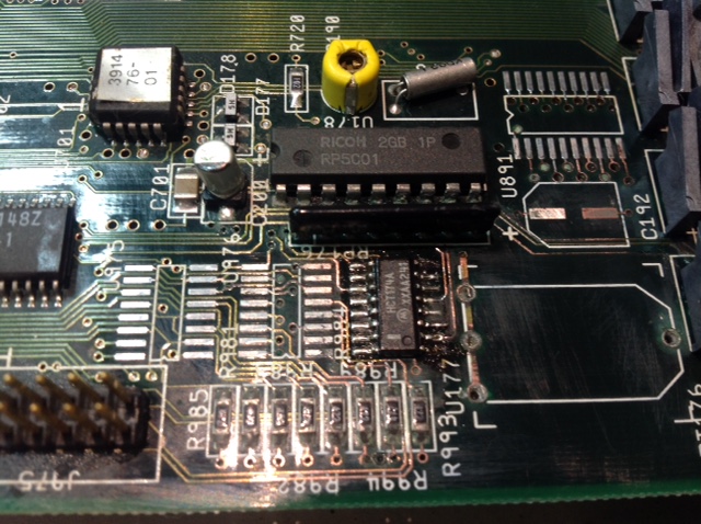
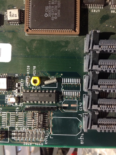



 Suffice to say that they work well and do not fail!
_small.jpg)
_small.jpg)
_small.jpg)